When you’re starting to become comfortable with designing in CATIA V5 you might realize that you spend a lot of time performing repetitive tasks that could be more suited for a machine. You would like to focus on innovation and creativity, and preferably have all the routine tasks be performed by someone else. Luckily for you this can be done, the “someone else” will be CATIA and Excel.
In this blog post I will show you how to connect CATIA V5 to Excel, and write a simple VBA macro, in order to take our first trembling steps towards design automation. We will look at adding automation in order to remove repetitive tasks connected to creating differently sized variants of a part.
The process will look like this:
1. Initial set-up of Excel
2. Create a master part
3. Define with parameters how the master part should be able to change
4. Write a VBA macro that controls the parameters
5. Create an Excel spreadsheet to use as Human/Machine-interface
6. Create as many variants of the master part as you wish
In order to get access to the Visual Basic editor we must make sure that the Developer tab is visible, do this by going to File>Options>Customize Ribbon and check the box next to Developer.
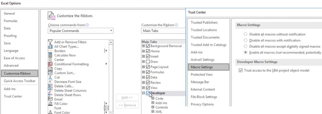
While still in the options window, go to Trust Center>Trust Center Settings…>Macro Settings and enable all macros as well as check the Trust access… box. OK your way out and we can get into the Visual Basic editor.
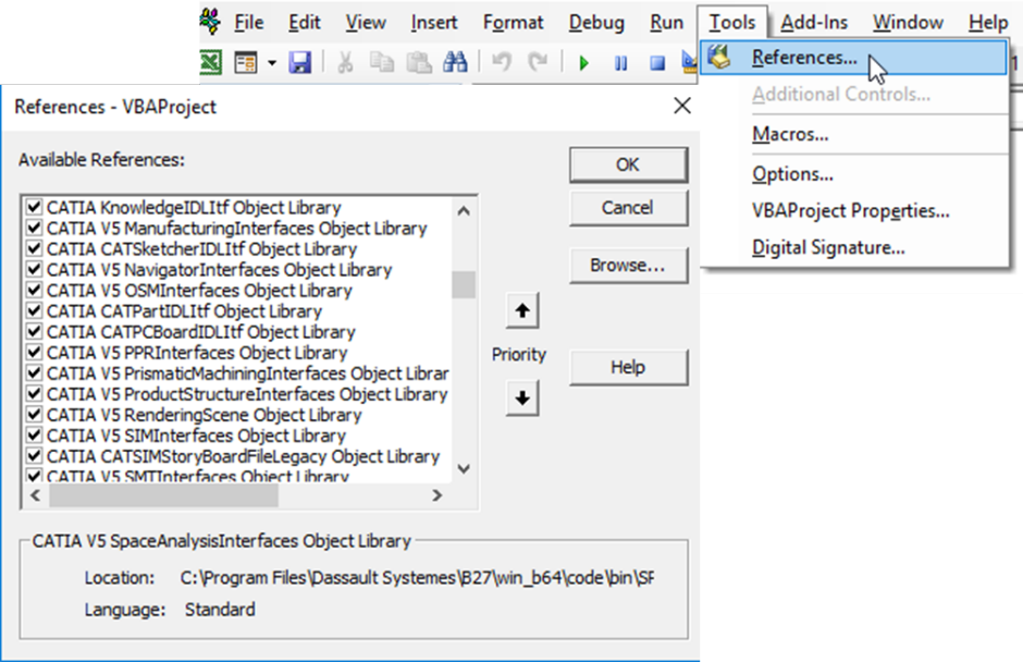
Open the Visual Basic editor from the Developer tab and choose Tools>References, here we will have to check all the boxes that start with CATIA, there’s a lot of them so patience will be required. When all those boxes are checked we are ready to write a VBA macro and apply it to our part.
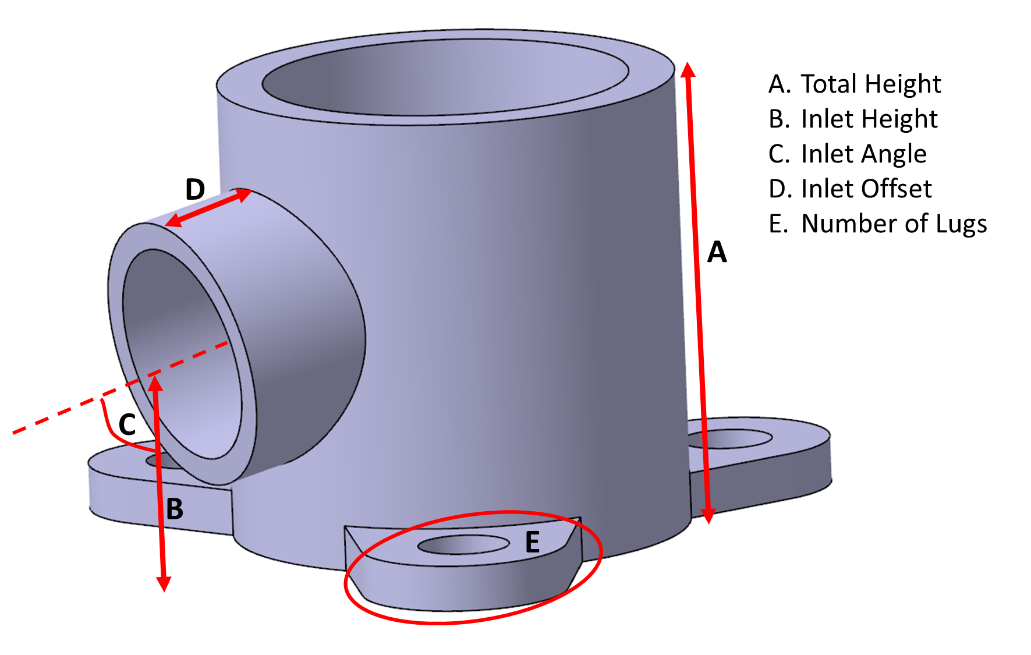
The part I will be using is a type of T-connection, its size and position of the interfaces are of interest, as well as how many screw lugs we want to use. In the picture below you can see which parameters I have defined to control the design.
With the Excel connection set up and the master part prepared we can start writing our macro. The procedure is quite simple, we insert a new module in the editor by right-clicking and selecting Insert…>Module. Then we need a couple of lines that direct the macro to the correct CATPart and then we can add all the modifications that we want. The code can be seen below.

The lines with the Set prefix create the necessary environment, the following lines assign values to the CATIA parameters by retrieving values from specific cells in an Excel spreadsheet, last the part is updated. If you want to assign values to specific cells in the spreadsheet from the CATIA parameters, i.e. retrieve an output, you just swap the positions relative to the equal sign.
The spreadsheet interface looks like below, the cells specified in the macro is used as our input boxes and as a nice touch you could add a button to run the macro instead of switching between the spreadsheet and editor window.
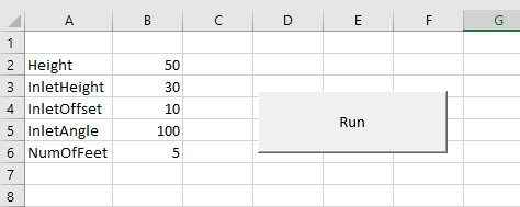
Now I can create all the variants I need by only changing the values in the spreadsheet. The more parameters we add, the more we can control. You only have to remember that in order to give more of the repetitive tasks to macros, the more robust the model needs to be.
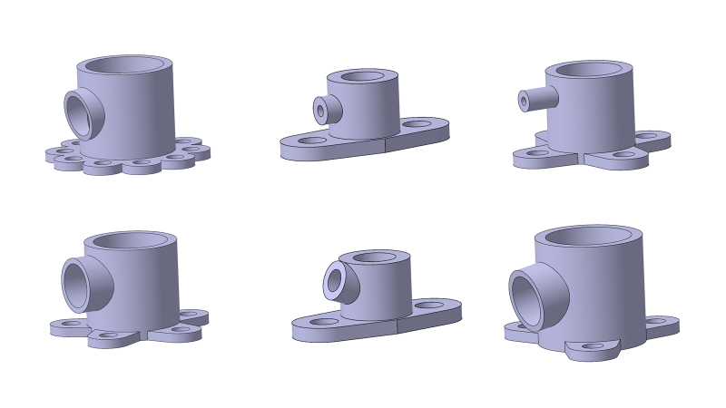
If I wanted to get more value out of this macro connection, not only the time saved by not having to design the different variants of the part manually. But also use the connection to find a better design, I could let an optimization software take control of the parameters and run the macro to find the optimal trade-off between my key performance metrics, for example weight and internal volume.


